![]()
Grave Jumper
![]()
The Grave Jumper is the first animatronic that I ever built but this project will explain how to build the new version. Its a different design that is cheaper and more stream line then the original that I built back in 1998 which was retired for the 2008 season. The Grave Jumper would be place behind a prop like a tombstone and then pop up behind it when activated. As always read the entire project first before purchasing any parts.
Construction list:
1. 1inch wide, 1/8inch thick aluminum bar that is 8 feet long, which can be bought at Home Depot in 8 foot lengths.
2. 1inch square aluminum tubing, which can be bought at Home Depot in 4 foot lengths, located next to the aluminum bar. 4 feet piece will be plenty for this project.
3. 4 qty. 3/8inch 3inch long bolts.
4. 4 qty. 3/8inch locking nuts.
5. 16 qty. 3/8inch washers.
6. 6 qty. 1/4inch 1-1/2inch long bolts.
7. 1 qty. 1/4inch 1inch long bolt.
8. 1 qty. 1/4inch 2inch long bolt.
9. 8 qty. 1/4inch locking nuts.
10. 1 qty 1/4inch hole size 1/2 long nylon insert. (This can be found at Home Depot)
11. 1 qty 3inch conner braces. (This can be found at Home Depot, 2pack)
12. 1 qty 2inch conner braces. (This can be found at Home Depot, 2pack)
13. 1 qty. 3/4inch diameter wood dowel. 3 foot piece will be plenty for this project.
14. 1 qty. 3/4inch thick, 2feet long, 1foot wide plywood. (Can be bought in 2foot square pieces at Home depot)
15. 1 qty quick disconnect fitting to hook up to you air line. (buy the one that fits your air line)
16. 1 qty. brass barb fitting for 1/4inch size tubing and will fit your quick disconnect fitting.
17. 1 qty. 1/4inch ploy tubing. (Comes in 25foot lengths from Home Depot)
18. 1 qty. 2-way air cylinder 3/4inch bore, 5inch stoke. McMaster part# 6498K348
19. 1 qty. Pivot Bracket for 3/4inch bore air cylinder. McMaster part# 6498K72
20. 1 qty. Rod Clevis for 3/4inch bore air cylinder. McMaster part# 6498K42
21. 1 qty. flow control for air cylinder. McMaster part# 62005K224
22. 2 qty. Breather vents. McMaster part# 9833K21
23. 2 qty. 1/8inch Push-to-connect tube fittings. McMaster part# 51025K177
24. 1 qty. solenoid valve Mac part# 111B-111BAAA This valve can be purchase through Action Automation & Controls Inc. or any Mac valve distributor. You can also use a different brand of 3 way solenoid valve with similar specs.
25. 1 qty. Power Cord for solenoid valve.

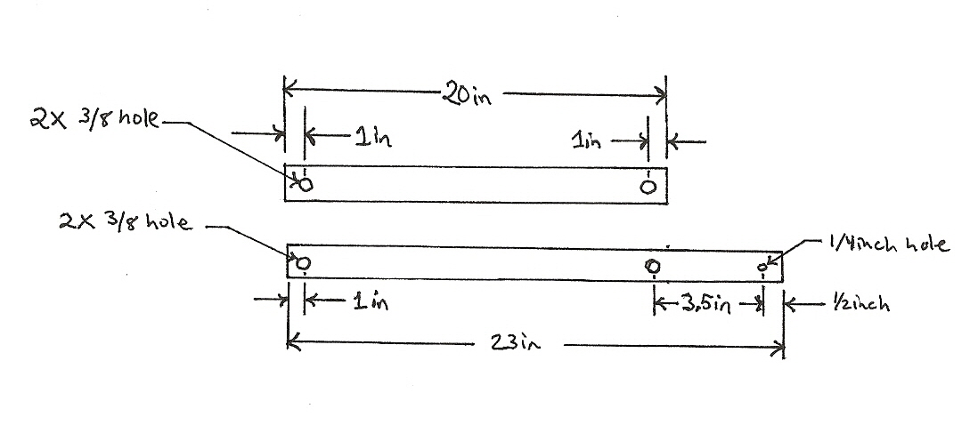
To start off the project the aluminum bar will be cut to length. Diagram left shows the correct length for all the bars. Cut two of each bar shown on the left for a total of four bars. These will be used for the arm on the Grave Jumper.

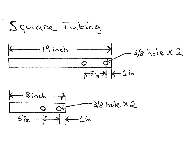
The diagram on the right shows the sizes for the square tubing. Cut one piece of each.
On the right the assembly of the Grave Jumper. Using 4 qty. 3/8inch 3inch long bolts and all 16 washers. The washers are used as spacers between the bars and tubes, four washers are used for each bolt. The wood base size is 2feet long by 1foot wide and I have spray painted all the parts black at this point.
The bottom L Bracket that is used in the picture does not give them enough support for the vertical square tubing. Another method using corner brackets works much better. Picture below of a set of corner brackets I bought at Home Depot. In upcoming pictures the brackets will be seen.
Picture on right shows the corner braces used. There’s one 2inch brace and one 3inch brace. The 3inch brace is used for support toward the front and the 2inch brace is used for side support (opposite the valve). A better picture of this will be seen later on.
These are the mechanical parts that are used to operate the Grave Jumper. Next section will explain how all these parts go together.

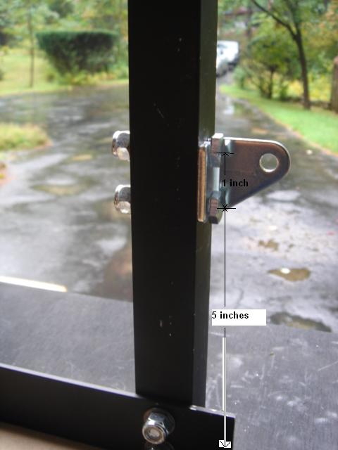
To start of the mechanics for this project the first thing that is done is to attach the pivot bracket where the air cylinder will be placed. The pivot bracket comes with a left and right piece but only the right piece is used. The location of the hole on the square tubing closer to the wood base is 5inches up and the second hole up from that is 1inch. I attached the bracket using two 1/4inch 1-1/2inch long bolts and locking nuts.
Air cylinder comes with a pin that is press fitted into the bottom of the cylinder, this needs to be removed. Using a vise an a bunch of washers as spacers the pin can be pushed out and a 1/4inch 1inch long bolt will be used to attached the air cylinder to the pivot bracket as explain in the last step. Three pictures below showing the process of the pin removal.
Attaching the air cylinder at the top is using a 1/4inch 2inch long bolt and a two spacer rings. I bought one spacer a 1/2inch long and cut it in half to space the Rod Clevis in the center of the bars. I used a 1/4inch locking nut with a lose fit so there is no extra friction on the Rod Clevis.
Below layout of the spacers.
At this point I added a piece of 7/8 diameter dowel 1foot long to mount a head to the front. This dowel can be any length you want to meet your needs.
The valve used for this project is a 3 way valve meaning that there are three ports. Input, output and exhaust. To start off screw in the two push-to-connect tube fittings (input, output) using a wrench to tighten them. Then screw in the breather vent to the exhaust port. This breather vent is used to keep any dirt or dust from entering the exhaust and damaging the valve. Also you will notice there is a second breather vent screwed into the bottom of the air cylinder as well. The valve is bolted to the side of the square tubing using two 1/8inch, 2inch long bolts. The placement of the valve is between the air cylinder pivot bracket and the corner braces.
The top of the air cylinder port has a flow control screwed in that controls the speed of the air cylinder by adjusting the flow of air. I also have cut a short piece of tubing to attach the valve to the air cylinder. The left over piece is used to tie into the air compressor. The power cord has been attached that will operate the valve.
Below plumbing fittings and tubing.
The picture on the left shows the barb fitting has been screwed in the quick disconnect fitting and pushed on to the tubing. I chose a female fitting that works for my setup but any type of fitting can be use that works best for your setup.
This is what the grave jumper looks like when it is done. The devil head that I used I got from Haunted Props.
Let me know if you have any questions on this project at feedback@haunteddriveway.com
The Haunted Driveway
Dedicated to Home Haunters