![]()
Flying Witch
![]()
The Flying Witch project is a full scale witch that stands on the ground and when activated will fly up into the air toward your guests. This is my most popular animatronic. This project will require compressed air to operate.
The main supplies needed is listed below and there will be a few screws, nuts and bolts left out of this list because sizes needed will rang differently depending on parts that you use but you will be informed in the instructions what you will need. I would advise to read through the whole project first to see what’s involved before you buy any materials.
Lumber
2, 2 x 4 that are 7ft long
2, 2 x 4 that are 5ft long
5, 2 x 4 that are 32.75 inches long
2, 2 x 3 that are 5ft long
1, 1 x 2 that is 3ft long
1, 1 x 4 that is 4ft long
Aluminum Square Tubing
2, 1 x 1 that are 8ft long
2, 1 x 1 that are 5 ½ ft long
2, 1 x 1 that are 13 inches long
You will end up buying four 8ft long pieces of 1inch square tubing and cutting to size. This tubing can be found at Home Depot.
Pneumatics:
A 2way 2inch bore air cylinder with a 14inch stroke.
2, flow controls that fit on to the air cylinder with a 3/8inch quick disconnect
3, 3/8inch quick disconnects with a pipe fitting that will fit your solenoid valve
A 4way solenoid valve that runs at 120volts
A quick disconnect with a barb fitting added so that you can attach this to the end of the white tubing which will then connect to your air compressor
25ft of 3/8inch white tubing (the kind they use for refrigerator ice makers) this you can get at Home Depot.
All the pneumatics except for the tubing was bought on Ebay. I will go into detail where to buy the pneumatic parts in the pneumatic section of this project.
Screws and Bolts:
A box of 3inch long deck screws
4, 3/8inch bolts that are 4 inches long
4, 3/8inch locking nuts for bolts
8, 3/8 inch washers for blots
2, 1/2inch bolts that are 5 ½ inches long
2, 1/2inch locking nuts for bolts
6, 1/2inch washers for bolts
Miscellaneous:
Black paint (for painting the whole animatronic black)
Witch mask and hat
Witch costume
Witch broom (I will tell you how to make one from scratch in this project)
Starting with the lumber the fame for the entire project will be built. Following the sizes listed above you will cut the 2 x 4 to the lengths given. You can also paint all the wood black and also paint the four 8ft pieces of aluminum square tubing at this time as I did.

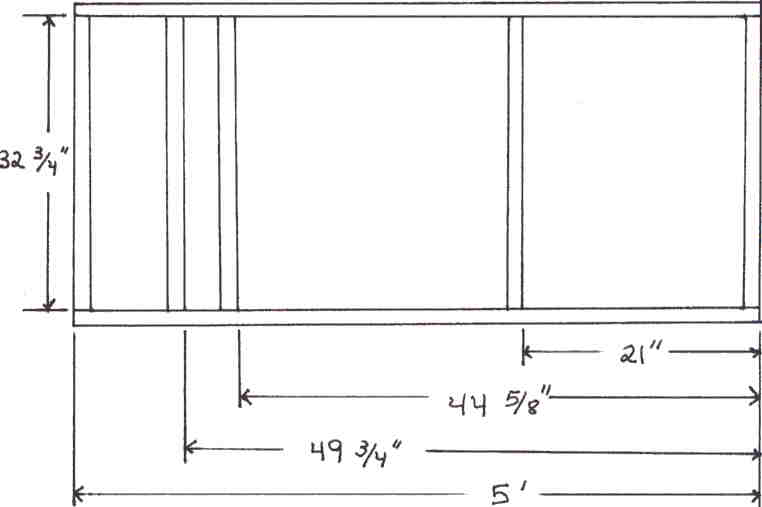
The picture on the right shows the layout of the 2 x 4 pieces. As you can see there are three 2 x 4 inside the fame and two of them are close together on the left side. These two pieces will support the vertical 2 x 4. I have included the distance on how far apart they both should be. To make sure that the vertical 2 x 4 fits sung take some wood that tis left over and use as spacer blocks to get the right distance. In the next picture the fame is going together and the spacer blocks are visible. It is important to get this distance correct even though I have measured out the distance you should still use the spacer blocks to get the correct width of the 2 x 4 for any regulates in the wood.
Picture on the right shows the fame going together with spacer blocks being used. The spacer blocks are left over 2 x 4. This frame is being put together using 3inch long deck screws.
The two 2 x 4 that are 7ft long need to have two 1/2dia holes drilled to receive two 1/2 bolts that will support the aluminum square tubing. To make sure the holes are in the correct places, both pieces need to be clamped together and this way you will only need to drill two holes instead of four. In the picture there are two holes drill which pass through both 2 x 4. The hole that is at the end is 1inch down from the edge. The second hole is 10inchs down from the center of the first hole drilled. Both holes are centered on the 2 x 4.
There are two spacer blocks that make a gap between both 7ft long 2 x 4. This is the 1 x 4 piece of wood that is used. The 1 x 4 piece is ripped down to the same width of the 2 x 4. In the picture you can see the bottom spacer block used to keep the 2 x 4s separated with a 1inch gap. The second spacer block used is 13inches long and is 38inches up from the bottom block. The second block is used to give added support to the air cylinder that will be attached in that area. Both spacer blocks are screwed into the 2 x 4s and will not be removed. The vertical 2 x 4 sandwich is centered in the frame and is screwed into place using deck screws making sure it is perfectly vertical. Make sure the holes drilled earlier are at the top.
The square tubing will go in the 1inch gap later on.
The picture on the right shows the two vertical 2 x 4s and the second spacer block is located in the red rectangle. There is a C clamp used to keep the 2 x 4s together while the second spacer block is positioned. Also you can see the holes drilled earlier are located toward the top. This vertical mass will be the pivot point for the large arm.
Next the frame will need some added support for the vertical mass. In the picture on the right there are two 2 x 3’s side by side attached to the bottom 2 x 4 and attached to the vertical mass half way up. To get the angles cut correctly line up the 2 x 3 on the side of the 2 x 4 at the top and transfer the angle with a pencil. Cut the top angle and then line it back up. At the bottom use a scrap piece of straight wood and line it up with the side of the 2 x 3 and against the 2 x 4 and transfer the angle using a pencil. Even if your angles are a little bit off it will still hold together with no problems.

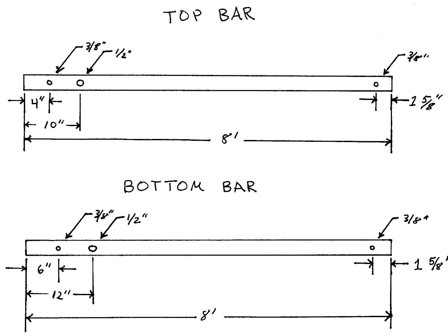
The arm that will be moving the witch up and down is made up of the aluminum square tubing. The picture below shows where the holes need to be drilled in both 8ft sections of tubing. There are two sizes of holes 1/2inch and 3/8inch. The top and bottom pieces have holes in different places even though they will line up once they are put together which gives an offset of the two. All holes are centered on the tubing.
Once the witch starts to fly up it will tip forward as it goes from a standing position to a diagonal position that's why the holes are in different places on the tubing.
Here are some overview pictures of the project so far. In the picture the square tubing has been put into place. The 8ft sections are part of the arm that makes the witch fly into the air. The two vertical pieces of tubing in the form is where the body of the witch will be mounted. At the top back there is two short pieces of vertical square tubing and this allows the air cylinder to create a equal amount of force on each of the two 8ft sections of square tubing.
Up next I will show how to make the front and back vertical tubing pieces.
The back vertical pieces add support to the arm by distributing the load equally on both 8foot sections of square tubing. The two 13inch long pieces are cut from one of the 8foot pieces that has not been used yet.
Square tubing length is 13inches
Two 3/8inch holes that are 1.5 inches from both ends. I would suggest clamping the two pieces together so you will only need to drill two holes instead of four. All holes are centered on the tubing.
The silver aluminum connector on the bottom bar will be used for connecting to the air cylinder. I will get more into this later on.
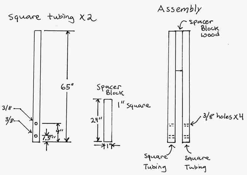
The picture on the right shows the two vertical pieces of square tubing in how they attach to the arm. There is a 4inch long 3/8 bolt with two washers on each side of the arm and then another washer and a nut would complete the hook up and the same happens with the bottom bolt. The picture below shows the dimensions for the vertical square tubing and you will need two of these. Also there is a spacer block that keeps the two pieces of square tubing together at the top. The spacer block is a piece from the 2 x 3 that has been ripped to a piece that is 1 x 1 in size two match the dimensions of the square tubing. The spacer block is important because this is where we will be attaching the witches body. To attach the wood block to the aluminum tubing there needs to be three holes drilled on both of the square tubing parts evenly spaced and the holes must be smaller than the wood screw to firmly hold the wood tight against the tubing. Take a look at the picture below it shows the size of the square tubing, spacer block and the assembly.

In the picture on the right the spacer block is at the top of the assembly and produces a 1inch gap between the two pieces of square tubing. The arm will sit in this gap and attach with the 3/8 bolts and washers as seen in the above picture.

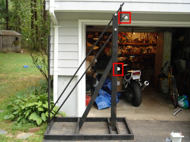
Both ends of the air cylinder will be attached to the two pivot brackets that are shown in the red boxes in the picture on the right. These two brackets I had to make because I was not able to get the customized brackets that are for this pacific air cylinder. The exact parts that are needed are listed below with there part numbers. The pivot brackets and the rod clevis can be home made. But if you can get your hands on those two parts go ahead and used them it will cost you around $30. The air cylinder if you buy it from a dealer will cost $110 but you can buy all of these parts for half the price or more by looking for them on Ebay like I did. If you can't find the exact parts look on Ebay to find parts that are close to what are needed and just make the adjustments to your project.
All parts are from Bimba
Air cylinder used is a Bimba 2inch bore cylinder with a 13inch stroke. Part # 3113-DXP
Pivot Bracket Part # D-620 you need two of these
Piston Rod Clevis Part # D-231-3 you need one of these
The above mentioned pivot bracket and piston rod clevis can be bought from McMaster-Carr off there website very easily if you can’t get the parts direct from Bimba. The parts are not made by Bimba but they are the same dimensionally and will work as good substitutes. Pivot bracket is McMaster part # 6498K564 The piston rod clevis is McMaster part # 6498K554
The right picture shows the home made pivot brackets that where made up. It is 1/4inch thick aluminum channel that is 2 x 2inches which I got a scrap piece from my local machine shop. Each bracket is 2inches long and the top has been rounded to match the bracket size. The bracket showed on the right has a 3/8 hole drill in the center of the arch. The brackets can really be made any way you want them to be if you don’t want to buy them. I ended up drilling two 3/8 holes in the bottom of the bracket and two holes that line up on the square tubing to ultimately attach the bracket.
The picture on the right shows part of the air cylinder and how it attaches to the arm. The aluminum block attached to the rod of the air cylinder is home made. It has a 1/2inch taped hole that the air cylinder rod screws into and a second perpendicular 3/8inch hole that ties in with a bolt that goes through the bracket.
The picture on the right shows the bottom pivot bracket. One 3/8 hole needs to be drilled close to the edge like the one in picture that has the bolt going through. The second hole that is on the edge in the middle is not currently used, do not dill this hole.
The picture on the right shows how the air cylinder attaches to the lower pivot bracket. Also the bracket is attached to the wood using five deck screws in an X pattern.
The picture on the right shows the air cylinder. I have screwed in a flow control to each port. The flow control is design to adjust the air flow into the air cylinder resulting in controlling the speed at which it moves. The picture above shows a closer look at the bottom flow control.
The flow controls used and all pipe fittings are from Nestech and you can purchase there fittings on there Ebay store. Go to advance search on Ebay and search for the seller armhammer.
Fitting used:
2 Pneumatic (air) fitting-3/8”tube X 1/4” NPT flow controls
3 Pneumatic (air) fitting-3/8”tube X 3/8” NPT elbow
Its around $13 total for these five fittings. Important the elbow fittings chosen are to fit the solenoid valve that I used. If your solenoid uses a different NPT size make sure you buy the correct one. Also if you were not able to get the same air cylinder that I used make sure you get the right size flow controls to fit your cylinder.
The picture on the right shows a 4 way solenoid valve. This valve I found on Ebay for $12. A 4 way valve that can handle 100psi and runs at 120volts is what is needed for this project. In the picture you can see I have gone ahead and attached the elbow fittings.
All fitting for this project have been sized to fit 3/8 tubing and these are quick disconnect fittings so you just take the tubing end and stick it into the fitting and it locks in place.
The picture on the right shows the solenoid valve mounted to the frame and the 3/8 tubing has been secured to the valve. The two tubes going up lead to the air cylinder while the one tube going down leads to the air compressor.
This picture shows what the whole setup looks like with all the pneumatics done.
This is the part of the project where the witch will be built and mounted to the front of the arm. Pick out a witch mask that you would like to use and stuff the head with newspaper or used that expanding foam in a can, like I did. This is where the wood spacer block comes in to use. The entire skeleton for the witch is attached to the spacer block using scrapes of wood. It's easier to attach wood to wood then wood to metal. I bought a 10ft long roll of chicken wire used to make the body of the witch. I just bent and molded a piece of chicken wire to make up the torso. I mounted the mask first using a scrap piece of 2 X 3 attached to the spacer block using some L brackets. But you could always attach the head using some screws in the back as well.
The picture on the right shows the back of the witch installing arms. I ended up just measuring my own arm and using those measurements to cut some 1 x 2 wood screwed it into a piece of 2 x 2 wood that I used for the shoulder. I measured my own shoulder and used that length for the witch.
I decided to make the left arm at a 90 degree angle and the right arm at a 45 degree angle.
I continued to make the lower half of the witch using the chicken wire and some scrap 1 x 2 wood to add spacers to staple the chicken wire to.
Using a small piece of chicken wire I beefed up each arm to show some thickness and I put on a black robe costume that I pick up at a local Party store. I also bought some witch hands that will be used to hold on to a broom.
The broom is made of a tree branch that I found in my back yard and a grass skirt I got at the local Party store.
In the picture on the right I rapped the skirt around the bottom of the branch Upside Down and stapled it. I then flipped the skirt over its self and this in turn hides the seam. I then took a short piece of rope and wrapped it around the top of the skirt to give it an old look.
The picture on the right shows what the broom looks like when it's down. I then attached the broom to the witch by lining it up with spacers I attached the chicken wire to. I also took some black spray paint and lightly darken the broom to give it a dirty appearance.
This is the finished project below and I added a witch hat that had some built in hair that I bought on Ebay.
The Haunted Driveway
Dedicated to Home Haunters